Wednesday, December 3, 2014

Flashing GL865-QUAD's firmware

If you bought a GSM Click board from MikroElektronika, chances are that the GL865-QUAD modem comes with older firmware. That might work for you, but my board came with version 10.00.144, which doesn't support SSL.

The GL865-QUAD chip can be easily upgraded via its AUX serial interface. Note that the AUX port is not the same serial port we use to operate the modem normally via AT commands, and it's actually not broken out to external pins so a bit of soldering is required.

Set up


A quick look at the datasheet reveals the location of the TX/RX pins:


I used a couple of breadboard jumper cables soldered directly to those pins:


To communicate with the GL865-QUAD I used this FTDI USB-serial converter from Sparkfun. According to Telit's datasheet, the AUX port is 2.8V CMOS logic, so I bridged across the two pads next to the 3.3V mark on the FTDI board with a bit of solder:


The GL865 hardware guide states that the absolute maximum input on 2.8V CMOS pins is 3.1V. I found the output of the FTDI chip was slightly over 3.1V, so I simply tied the TX/RX pairs together and hoped for the best. It turned out okay, but if you want to be extra careful, I suggest you use a simple level converter like this:

GL865 pin 45 (TXD_AUX) -------------- FTDI RXD
GL865 pin 44 (RXD_AUX) ----+---|<|--- FTDI TXD
                           |  1N4148
                           /
                           \ 4K7
                           /
                           |
GL865 any GND pin      ----+--------- FTDI GND

The diode will provide the necessary ~0.6V drop so that the FTDI output is within safe levels while the resistor pulls the CMOS input down to 0V when the FTDI TXD outputs a logic 0.

My whole setup looked like this:


Besides the RX/TX cables, I tied both the GL865 and FTDI grounds together (blue cable), and of course you need a 3.3V source to power the whole board. I used some batteries and a 3.3V regulator for this (not shown in the picture above).

Get the firmware


As of today, the latest firmware version is 10.01.140. It's not publicly available neither on Telit nor MikroE's websites, but you can request it directly through MikroE's contact page. Ask them for the XFP tool, too. They answer within 24 hours. The XFP tool runs on Windows, if you are on Linux or OS X you can run it from a Windows virtual machine.

Flash the firmware


With the GSM Click powered off, load up Xfp, select the firmware and hit program. As soon as Xfp says "Linking", power on the GSM Click. It has to be done in that very order. If you hit the program button after the Click has booted, Xfp will stay in a never ending "Linking" loop. It takes about 10 minutes to finish:


Test it!

To check the firmware version you can use the AT+CGMR command, which should output something like this:

--> AT+CGMR
<-- 10.01.140\r\n

And... done!

Friday, August 8, 2014

GSM Click + Arduino

I'm working on a hobby project that involves sensing environmental data and uploading it to the Internet using Arduino and a GSM/GPRS receiver. There is a range of GSM shields and standalone modules to choose from. For this particular project I went for the GSM Click module from Mikroelektronika. It's probably not the most affordable GSM module out there but I like it because it has a nice protoboard friendly layout and a smallish footprint. It's also widely available (I've got it from Newark CA).

Mikrolelektronika actually has two modules that are similar, the GSM Click and the GSM2 Click. Each one is based on a different GSM chipset (Telit on the GSM, Quectel on the GSM2), but both are quad-band and support GPRS.

The interesting thing about these modules is that they have a full TCP/IP stack built-in, and they even support high level protocols such as HTTP and DNS. Imagine implementing all that in an Arduino with 32K of flash and 2K of RAM... So the workflow for an HTTP request in these modules is actually very simple:

  1. Unlock the SIM via PIN
  2. Wait for network registration
  3. Start a GPRS connection
  4. Open up a connection to your server:port (ie. google.com:80)
  5. Send / receive data
  6. Close the GPRS connection
Steps 1 and 2 are done during initialization, and as long as the module stays registered, new requests would only require 3..6. Most of the steps can be done with single AT commands.

Electrically, I/O pins in the GSM Click support both 3.3/5V levels, but it does require a 3.3V power source. It took me an hour of frustration before I realized this. According to the datasheet of the GL-865 chip, the module can draw a maximum average ranging 140-330 mA (depending on the band and GPRS class), however they state the power supply must be designed to withstand a peak demand of 2A. This means you can't use the 3.3V source from most Arduinos because they are rated for much lower current, you need to provide your own 3.3V regulator.

The module comes preconfigured for 3.3V I/O operation. If you want to connect it to 5V devices you need to unsolder an SMD jumper and then resolder it across the 5V label.

In addition to the 3.3V power source you also need 5V (you can take this from the Arduino, it's used just for level conversion), GND and TX/RX. The module's TX goes to the Arduino RX and viceversa.

I've used SoftwareSerial on pins 2/3 to talk to the module so that I have the hardware UART free for debugging. However, when using both ports at the same time, incoming data from the GSM module gets massively corrupted. I believe either of them alone would work fine, but it's still early to say.

In the next post I'll show a more detailed connection schematic and some test code to do basic HTTP communication.

Monday, April 7, 2014

Changes in firmware 1.5

Version 1.5 of the Trackuino firmware is out! It fixes some bugs reported mainly through email and the hab-ham forums.

One of the longest-standing issues was compilation with Arduino 1.0+. This has been fixed in many forks out there, so it was about time it made it to the official code. The 1.5 firmware has been tested with the following IDEs:
  • Arduino 1.0.5 (build tested on an Arduino Duemilanove)
  • Arduino 0023 (build tested on an Arduino Duemilanove)
  • Mpide 0023-20130715 (build tested on a Chipkit Uno32)

Another issue was regarding readability of the signal. You can read this thread for background, but in essence some TNCs have problems decoding the signal when there is a significant amount of imbalance between the 1200 and 2200 Hz tones, no matter how clean the signal is in SNR terms. This problem has been thoroughly described by John Ackermann N8UR in this article.

The problem boils down to the following: usually FM transmitters emphasize the high frequencies of the base band. They do so to improve the immunity to noise and overall SNR of the signal. To counteract this effect, receivers, in turn, de-emphasize the received signal so that the end result is a spectrogram that closely resembles the original.

HX1 modules, however, don't have such a pre-emphasis network. Thus, the power of the 1200 and 2200 Hz tones is distributed equally over the air, but receivers will attenuate the 2200 Hz tone largely, resulting in a signal that some TNCs can't decode. Here is a an example of a Trackuino transmission received by an Icom IC-229H, then fed to my poor man's oscilloscope (Audacity). See the amplitude difference between the two tones?


Now, when you transmit from a balloon, the coverage area will be huge even for 300 mW, so chances are that some receiver or another will successfully decode the signal. On the ground, however, your packets might struggle with local receivers.

The solution is to de-emphasize the 1200 tone, which translates into an emphasis of the 2200 one in relative terms... It's impossible to boost the 2200 either in circuitry or in software because the HX1 is already being driven through its full 0..5V range. This will bring other issues like FM undermodulation (the received amplitude will be lower), but it should improve the overall equalization of the signal.

The same transmission with relative emphasis of the 2200 tone:


Pre-emphasis can be turned on in config.h by setting the PRE_EMPHASIS flag to 1, and is now the default setting.

The other issues addressed by this version are:

Baud rate accuracy

Due to accumulation of rounding errors in the modem code, the baud rate was actually 1201.92 bps on 16 MHz Arduinos. This is within the tolerance of all the receivers I've tried, but it could get worse depending on the actual CPU clock. Version 1.5 uses fixed point arithmetic to achieve a baud rate that is consistently closer to the nominal 1200 bps regardless of the clock speed (1200.03 bps @ 16 MHz).

Simpler modem ISR

I've slimmed down the modem ISR so that the chances of interrupt overrun are lower. The AFSK code now runs asynchronously in the main loop and the samples are fed to the ISR via a FIFO queue. This makes the AFSK code easier to debug, too.

If you have any question or bug report, you are welcome to post it in the hab-ham forums.

Tuesday, August 28, 2012

New shield (2.2 BETA) and firmware (1.4) are up

If you have tried to build a Trackuino board, you will have noticed that the Venus GPS part from Sparkfun (GPS-09133) has been retired and replaced with GPS-10921, which has in turn been replaced with GPS-11058.

Unfortunately, the engineers at Sparkfun have deemed necessary to reshuffle the pinout and make the newer board incompatible with existing designs that used the older boards, including Trackuino. I'm still puzzled at this decision, this is like the 7805 reversing in and out just because it "makes more sense".

If you already have a board designed for GPS-09133 or GPS-10921 and want to use GPS-11058, there are two solutions: either run small cables instead of pin headers, or build a small adapter board to rearrange the messed-up pins.

The GPS chip has also been replaced (634FLPx becomes 638FLPx), but this should not be a problem.

Although I plan to run away from this problematic part, I have uploaded the Eagle files of a new design that is compatible with GPS-11058. Look for trackuino-shield-2.2.zip in the downloads area.

I have not tested this design yet. I will remove the "BETA" label as soon as I get some boards tested.

Since I haven't built any 2.2 board yet, all I can show is this nice 3D rendering from mayhem labs:

The complete feature set of the Trackuino Shield 2.2 is:

  • Replaced Venus GPS 634FLPx (sparkfun #9133) with newer 638FLPx (sparkfun #11058).
  • Auto 3.3/5.0v operation for Chipkit Uno32 compatibility
  • Eagle files converted to 6.x format.
  • Use Arduino's own 5V regulator to power the HX1.
  • Replaced TO220 3.3V regulator with SMT + board sink.
  • Added bleeder resistor for passive piezo speakers.
  • Battery (Vin) sensing (through a resistive voltage divider).

Matching this new shield, there is also a new firmware version: trackuino-firmware-1.4.zip in the downloads area. The new features are:

  • NEW: Support for PIC32 / Chipkit Uno32 platform
  • NEW: Support for active or passive buzzers (DC or PWM driven)
  • NEW: Battery voltage sensing
  • NEW: Slotted transmissions for multilaunch events
  • REMOVED: Support for the MX146 radio

Find more information in the project page at google code, and enjoy!

Saturday, December 17, 2011

The amazing flight of K6RPT-11

Wow!

This was about 3 days ago. The California Near Space Project (CNSP) team launched 4 balloons. Two of them were short-duration, high-altitude flights. The other two were long-duration floaters (K6RPT-11 and K6RPT-12). First, the announcement:

http://www.tapr.org/pipermail/aprssig/2011-December/038028.html

Quote:

Our goal is to reach neutral buoyancy at a very high altitude and fly as far across the United States as possible.

Well...

The balloon not only made it through north america. It completely crossed the Atlantic, entered Spain through Jerez de la Frontera and exited towards Italy. After a 57 hours flight, it eventually descended on the Mediterranean sea off the coast of Algeria.

Captura de pantalla 2011 12 16 a las 09 33 40

Look at the green portion of the trajectory after the balloon passed New Jersey. These were quiet hours of uncertainty until the signal was picked up again from the Azores:

Captura de pantalla 2011 12 16 a las 09 35 37

Launch time was 2011-12-12 00:40:31z. The last packet was heard on 2011-12-14 09:46:30z:

Captura de pantalla 2011 12 16 a las 09 34 29

You can see the full trajectory on aprs.fi while it's recent:

http://aprs.fi/?call=K6RPT-11

Update: Below is a video of the launch:


Sunday, September 25, 2011

OSHWCON 2011

¡Gracias a todos los asistentes a mi charla sobre fotografía espacial en la conferencia OSHWCON 2011 y sobre todo a los organizadores por darme la oportunidad de exponer el proyecto! Espero que se repita y nos podemos ver con más proyectos el año que viene. Para cualquier duda me podéis localizar en el correo javi en trackuino punto org. ¡Un saludo!

(ENG: Thanks to all who attended my talk at OSHWCON 2011 and especially to the organizers for the opportunity to present my project! Keep it up and hope we'll see more projects coming next year!)

Tuesday, August 2, 2011

Important fix in version 1.31

Version 1.3 of the Trackuino firmware had a bug by which altitudes over 32767 feet would be rolled over to negative values. A new version fixing this issue is available in the downloads area. No extra features have been added, so your "config.h" from previous version 1.3 can be reutilized verbatim.


Saturday, July 30, 2011

How NOT to launch a balloon

The neck snapped when the balloon turned upside down. We were planning to release the load line slowly so that the strings would not rip through the payload box, completely oblivious that the weakest point was the neck of the balloon :(

Tuesday, July 5, 2011

Trackuino Shield

This is really exciting! Kyle Crockett has designed a new Trackuino shield. Just plug it on top of an Arduino board to turn it into an APRS tracker complete with GPS, a Radiometrix HX1 FM transmitter and a temperature sensor!

The whole thing is powered through the Arduino jack (7-12V), and the only external components needed are the GPS and radio antennas. The total footprint is much smaller than the previous board, so its price is also cut by more than half. And because all the Atmega pins are broken out to female headers, It can be easily extended by stacking more shields on top of it.

For now, you'll have to figure out the bill of materials from the Eagle schematic, but we'll post a proper BOM shortly. The SCH and BRD files can be downloaded from the project page.

Monday, July 4, 2011

Version 1.3 of the firmware is up!

Trackuino logoVersion 1.3 of of the Trackuino firmware is up in the downloads area! There are lots of improvements and fixes. Here is a summary:

Improved GPS compatibility

The previous GPS code made too many risky assumptions about the NMEA format, so it failed miserably on certain versions of the Venus 634FLPx (which, ironically, was the only supported GPS). Now the parsing routines are more tolerant to variations in the numeric formats, so compatibility with other units should be greater.

Signal quality (enter real-time computing)

In Packet Radio, the maximum bandwidth used by the AFSK carrier is 2,200 Hz. Nyquist tells us that we need at least 4,400 samples per second to properly rebuild the signal at the receiver, but that requires an ideal low-pass filter with a cutoff frequency of 2,200 Hz, which is neither physically achievable nor realistic in FM radios where the cutoff is usually higher, around 3,000 Hz. For those two reasons, oversampling is usually desirable (even if not mathematically necessary) if we want to avoid annoying harmonics that distort the signal and waste our scarce power.

The Trackuino firmware uses a 62,500 KHz sample rate, which is well away from the audible spectrum. Oversampling improves the quality of the signal at the receiver, but it requires pushing samples at a rate of 1 sample every 256 clock cycles (16 MHz clock rate / 256 = 62.5 KHz), so it's really taxing on the CPU. To make things worse, the Arduino is also busy doing a lot of equally important things, such as staying up to date with the GPS, keeping track of time so that millis() and delay() keep working as expected, and handling the buzzer (more on the buzzer later). All these tasks are interrupt-driven, which means they happen asynchronously without regard of one another or the normal program flow. The interrupts can be queued, but only one of each kind at a time. If an interrupt comes without having served the previous one, the second interrupt will be lost. So, not only has our modulator a meager 256 cycles to do its job, but it also has to struggle over the CPU with other interrupts...   When some task needs to be done under a deadline constraint such as this, it's called a real-time system. Efforts to ensure real-time operation are geared towards three goals:

  1. Priorizing the real-time task over not-so-important tasks. In the AVR architecture, interrupt priorities are fixed, so we can't do that.
  2. Keeping our real-time task short, so that it can meet its deadline.
  3. Keeping non-important tasks short, so that they don't hog the CPU while the important task is waiting.

There are a number of improvements in version 1.3 on those regards:

  • Serial (GPS) interrupt: The selfish implementation of this interrupt in the Arduino library spent an abusive 330 cycles on every received byte. It means that, for every received character from the GPS, chances are that one modem interrupt is lost altogether. Arduino version 22 has an optimization that cuts this time down to 80 cycles, so the code now enforces compilation under Arduino version 22 or later.
  • Modem interrupt: Some optimizations have been done to shave off a few cycles here and there. The modem interrupt should take 150 cycles max, average is less than that.
  • Debug information: By uncommenting a flag in config.h you can get useful information on overrun conditions.

Previous versions of had interrupt overrun issues, which translated into small variations from the nominal baud rate (1200 bps). Luckily receivers have some tolerance to baud rate deviations, so it's not that big a deal. In any case, the new version should improve the rate of successfully decoded packets.

SRAM usage optimization

The Atmega328P has 2 KB of SRAM, of which about 512 bytes were taken up by a huge sine table in modem.cpp. This table has been moved to the much more spacious program memory (32 KB). There are a few other candidates that scream to be moved to PROGMEM too, such as the APRS comment, callsigns and such, but these haven't been moved (yet).

Buzzer support

This should help in acoustically locating the payload. The buzzer is handled by timer 1 using PWM. Piezoelectric buzzers demand very little current, so they can be driven directly with pins 9 or 10. The tone frequency can be configured in config.h as well as the duty cycle in seconds. It doesn't make sense to have a payload beeping at 100,000 ft. since there is no air to begin with, so the maximum operating altitude can also be programmed.

CPU usage LED indication

This might look just cosmetic or geeky, but it's actually quite useful. The idea is that the LED will glow increasingly brighter as the CPU gets busier. For example:

  • If the AVR is idle, the light will be very dim. Tthe AVR is never really idle for long periods of time, since timers 0 (millis) and 1 (buzzer) are going off periodically.
  • When receiving data on the serial port, the LED will turn slightly brighter because it takes extra CPU to process the incoming bytes. This is a way of checking for GPS activity at a glance.
  • APRS transmission takes the most CPU, so the LED will be almost fully bright.

Monday, June 27, 2011

Intervalometer with CHDK

I wrote a script for Canon cameras with CHDK that works as an intervalometer. The script can take photos and videos alternately. The interval between photos, the number of pictures between videos, and the length of the videos in seconds can all be configured from the CHDK interface. It has other handy features like switching the LCD off to save power, or pre-focusing at the infinity so that the AF doesn't have to struggle with low contrast exposures at high altitudes.

CHDK is a firmware addition that enhances the camera functionality by giving more control over exposure, raw capture and display options, but most importantly for us, it allows scripted control of the camera. The scripts can be written in a derivative of BASIC called uBASIC, or Lua. You can control almost every aspect of the camera from a script, including filesystem manipulation, timed shooting, adjusting the flash or the exposure parameters, timed shots and even switching dial modes programatically. It's perfect for high altitude balloons because the camera can operate autonomously without any extra circuitry and does not require any attention from the tracker. Check out their web page for installation details. The firmware is fully reversible, you can remove CHDK by just reformatting the SD card and the camera will be back to normal.

The intervalometer script works quite nicely! I went to a fireworks display earlier today and captured 390 photos about 0.5 seconds apart from one another. The camera I used is a Canon A570IS set to manual mode, 0.4 seconds exposure, f/2.6 aperture, ISO 100, no zoom and pre-focused at the infinity with the intervalometer script. I assembled all the pictures together in a sort of time-lapse video and here is the result:

More on the intervalometer at the trackuino project's wiki. You can download the script (trackuino.lua) from the downloads area.

The script is largely based on CHDK's Accurate intervalometer with power saving and pre-focus and the Spacebits team's intervalometer. Most of the code is actually taken from them. I tried to make it compatible with other Digic III/IV cameras, but If the trackuino intervalometer doesn't work for you, make sure you check these out!

Monday, April 18, 2011

KJ6KUV-11 flight and successful recovery!

KJ6KUV-11 was launched yesterday from Ojai, California at 0820 PDT and successfully recovered 84 minutes later near Oak Park, 53.6 Km to the south-east! Check Kyle's blog for details, but I think all the efforts can be summarized with one single picture:

Earth

During the whole flight, the balloon was able to steadily report its position via APRS and the trajectory could be followed at aprs.fi. Between 12-16 Km altitude, the balloon caught the jet stream and sped up quite a lot as you can tell by the more spread-out points on the map!

kj6kuv-11 trajectory

The tracker was a Trackuino board with a Venus 634FLPx GPS and a Radiometrix HX1 300 mW radio transmitter. We were not sure the HX1 was going to deliver enough power to reach any digipeater from that high up. Well, sure it did... At its peak altitude (20 Km), the signal could be heard from Phoenix, Arizona, which is... 597 Km away!

kj6kuv-11 hx1 range

We were also not sure the Venus 634FLPx would report its position above 18 Km high, since many manufacturers seem to get the CoCom limits all wrong. But then again, the above picture proves how the GPS worked perfectly at 20036 meters.

Here are some flight stats I gathered with WBALTRAK. This is a plot of altitude versus time:

kj6kuv-11 altitude vs time

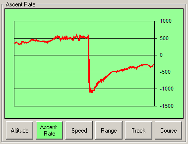
The ascent rate was smooth and constant at about 500 meters/minute. After the balloon popped, the payload fell at a vertiginous 1000 meters/min and steadily slowed down as the air density allowed the parachute to deploy. The payload landed smoothly at 294 meters/min:

kj6kuv-11 vertical rates

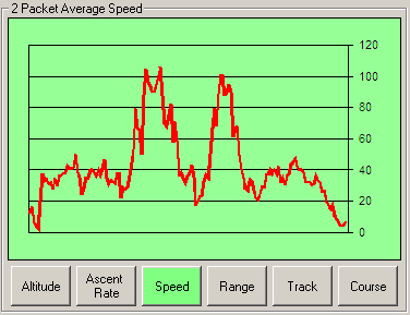
The speed was about 38 Km/h average and it reached peaks of 100 Km/h (about 60 mph) while the balloon was caught by the jet stream:

kj6kuv-11 speed

This was a lot of fun to track :)


Saturday, April 9, 2011

First Flight

I'm really excited to announce that Kyle (KJ6KUV), a great contributor to this project, is launching a balloon and he'll be using a Trackuino board to track its payload. He'll be launching from the Oxnard airport (California) on sunday april 17 around 8:00 am pacific time.

To track the balloon online go to this page. It will have the most recent position as well as the previous positions reported: http://aprs.fi/?call=KJ6KUV-11

Best of luck with the chase!

4 things

A few random updates:

1. I'll be giving a speed talk on Trackuino, high altitude balloons and near space photography at OSHWCON 2011! Quoting their web site:

The Open Source Hardware, Electronics and Robotics Convention is a 3-day event organized by the Synusia collective in an effort to extend the Open Source Software and to promote electronics and the philosophy of "do it yourself". The event will take place in Madrid at the Centro de Formación Padre Piquer,  from the 23 to 25 September 2011.

2. This blog is becoming a bit chaotic, with bits of information here and there. So, I'm giving the Trackuino project's site a facelift. From now on, technical articles will go to the wiki, while news and event updates will stay in this blog.

3. Even though the wiki is pretty much empty right now, I just posted an article on flight prediction based on Rick von Glahn (NØKKZ) great WBALTRAK software. Unlike on-line prediction sites, this program uses actual inflight data to predict the touchdown point with higher accuracy. Check it out, I think flight prediction is a key step prior to and during the flight of high altitude balloons!

4. Last, but not least, we're having our first Trackuino flight next sunday! But this deserves a dedicated post, so stay tuned!


Saturday, January 8, 2011

How to build your own Trackuino board

Update: the latest information on building the Trackuino board (with slight variations from the process described here) is on the google code project's main page.

Here is how to build your own DYI tracker solution based on the Trackuino firmware and Kyle's PCB. Building the tracker involves a bit of hackery at some points, but I'll try to make it as straight-forward as possible. This is how the finished board looks like:

trackuino_board_640.jpg

Features:

This is a summary of older posts, in case you just landed:

  • GPS: Venus 634FLPx. Supports > 18 Km according to their tech support (to be confirmed empirically)
  • Radio: The board supports Radiometrix's HX1 (300 mW) as well as Argentdata's MX146-8v (500 mw).
  • 1200 bauds AFSK using 8-bit PWM
  • Sends out standard APRS position messages (latitude, longitude, altitude, course, speed and time).
  • Internal/external temperature sensors (LM60) to read temperature in and outside the payload
  • Support for 1 capacitive humidity sensor
  • Cut-down "aka suicide" mechanism: you can hook up a nicrom wire and cut the payload line if your balloon gets stuck aloft for a long time.
  • ICSP header for in-circuit programming
  • 2 x SMA female plugs (1 x GPS in + 1 x radio out)
  • Open source (GPLv2 license), both software and hardware. In other words, do whatever you want with it: modify it, add it to your project, etc. as long as you opensource your modifications as well.

Which radio to pick?

hx1_or_mx146.jpg

Radiometrix's HX1 is cheaper, but Argentdata's MX146-8V is more powerful and thus has a better range. On the other hand, the HX1 version requires fewer components to buy and solder. My take? The HX1 is good enough.

How to build the board?

Both Eagle's schematic and PCB source files are here. You can do the exposure/development/etching process yourself, but I suggest sending it to a PCB house. I made the project public at BatchPCB, so anyone can go and order one. Their prices are not bad, but please comment if you find a better deal.

Components

Here is the bill of materials for the HX1 version and the MX146 version. See what I mean about the HX1 requiring fewer components? Also, these parts are in the schematic, but haven't found a clear purpose for them yet, so don't buy them.

How to build the firmware?

The easiest way is with the Arduino IDE. Download the latest "trackuino-ide-xxxxxxxx.zip" from here. Unzip it in your sketches directory.

Now, you'll have to change some settings. Open the "config.h" tab and:

  • Put your own callsign and SSID here. By default it's nonsense, something like "MYCALL". SSID 11 is good for balloons.
  • Select your type of radio here (HX1 or MX146)
  • Optionally, add some custom comment to the APRS messages, set a different TXDELAY, change the APRS update period (default = 61 seconds), etc.

Now open the trackuino.pde sketch, compile and flash.

If you're comfortable with command line tools, there is also a "trackuino-gcc-xxxxxxxx.tgz" version with Makefiles that you can compile with the gcc-avr toolchain. I like to develop using the gcc-avr toolchain because the IDE doesn't support multi-file projects quite well.

Testing!

Time to test the board! Plug the GPS and TX antennas and power the board. You need at least 6 volts for the HX1 version, and 9 volts for the MX146 version.

I have tested the HX1 version. If someone tries with the MX146, feedback will be very welcome!

And since a picture is worth a thousand words, take a look at this screenshot from APRS.FI and see how far this little HX1 can get. I'm successfully being digipeated by EA5ERC-15, which is an unbelievable 144.5 kilometers away! And I'm at sea level!

Captura de pantalla 2011-01-08 a las 20.29.54.png


Thoughts on on-line collaboration

On my last entry, I blogged about a schematic diagram to help those DIYers build their own tracker using the Trackuino firmware. Well, Kyle Crockett picked it up and generously built a nice PCB out of it. It blows me away how we're alive during the time when you can post the most vertical stuff on-line, reach out to those with the same interests as you, and find people across the globe willing to collaborate towards the same goal without ever having met in person... It really does.

IMAG0027.jpg

I'll be posting soon with details on how to get one of these boards manufactured and the bill of materials so that you can assemble it yourself.

Thursday, October 14, 2010

Schematic (II)

Hello! This is a second iteration over my previous schematic.

There are some additions:

Click on the picture to enlarge it, or just download the EAGLE .sch and libraries from my repository.

Friday, July 2, 2010

Using two balloons for controlled descent instead of a parachute?

It has always come to mind that using 2 balloons would provide a slow and controlled descent of the payload. Parachutes won't open at high altitudes because the atmosphere is too thin. So usually, after the balloon pops, the payload starts plummeting and spinning like crazy until it reaches an altitude where the pressure allows the parachute to open. During its crazy nose-dive, the payload, the load line and the parachute itself are very likely become an entangled mess with the whole thing hitting the ground at free-fall speed. Plus I fear the antenna will break as well.

How to prevent this?

Well, Kyle has reported his experience using 3 balloons. The theory is that when 2 of them pop, the 3rd one doesn't have enough lift and starts going down smoothly. I'm really looking forward to him elaborating more on his blog.

Also check out Todd's write up. He used a parachute and a ring to prevent the parachute lines from tangling during descent.

Wednesday, June 9, 2010

Schematic

This is my first attempt at designing the tracker board. It basically consists of a barebones Atmega328P, a GPS, a radio, temperature sensors and a cut-down (aka the "suicide") mechanism. Click to enlarge:

Also check out this pin mapping reference between the Arduino and the Atmega328P.

I wanted the option to use both the Radiometrix HX1 and SRB MX146 radios, so I wired them both, but only one can be really used at a time.

As you can see, the connection from the AVR chip to the HX1 is straight-forward, just wires and no additional components.

The MX146, however, requires a couple of BS170 mosfets to translate I2C's TTL 3.3 <-> 5v levels, a transistor to drive the PTT and a voltage divider to convert the audio input down to 500 mV peak-to-peak. The MX146 also has its own 8V regulator, since I've got the 8V version. You can absolutely leave these components out if you're only going to use the HX1.

The GPS is a Venus 634FLPx. I bought it from Sparkfun. Since this is a 3.3V device, it needs some level conversion (via the diode method described here) and its own 3.3V regulator.

I also added a couple of LM60 sensors, since I want to measure both on-board and external temperatures. The external sensor can be connected via a terminal block (X2). I also planned for a capacitive humidity sensor (X3), but I don't think I'll use it on my first flight.

A MOSFET 22nf031 controls the "suicide" mechanism that cuts the rope if the balloon somehow refuses to burst. It has its own power source (X5) to avoid draining the main Vcc, and the nicrom wire goes to yet another terminal block (X6).

Lastly, X7 is the main Vcc source, coming from a pack of lithium AA batteries.

I have the Eagle .sch file and libraries for the MX146, the Venus GPS and the HX1 if anyone is interested.

Next step: create the .brd file for a PCB house. I'm really struggling with this, since it must match the PCB house specs (I'm thinking Olimex).

Sunday, May 9, 2010

How I built my cheap 2m Yagi antenna

I wanted to build a Yagi antenna so that I could point it at the balloon and track it from the ground. Apparently, VHF propagation improves hugely with height so, if the balloon is high enough, even a low-gain omni antenna will pick it up. I did, however, not want to leave anything to chance, so I built the yagi even though I might not need it.

The antenna described here has a 8.8 dBd gain, ie. it has a 8.8 dB gain over a dipole, which in turn means the power of the signal will look 7.6 times stronger than if I were to use a regular dipole. This is what it looks like:

I used this great Yagi Calculator by John VK5DJ to design the antenna. The author says that the program is meant for long antennas (over 10 directors), but mine has 4 directors and it works great.

Here are the ingredients. This shouldn't be more than 10€ provided you have basic tools.

  • 5 square aluminum rods (1m long, 8x8 mm section) for the directors and the reflector. The cross section looks something like this: |_| (ie, one of the sides of the square is missing). I guess I could use fully squared rods, but they would be heavier.
  • 1 rectangular rod (2m long, 16x8 mm section) for the boom. I attached the elements to the long (16mm) side for stability. The cross section looks like this: |_|_|
  • 2 round, hollow rods (1m long, 6 mm thick) for the radiator. I think hollow ones are easier to bend, and lighter too.
  • 1 round, hollow rod (1m long, 8mm thick). The 6mm rod must fit into the 8mm rod.
  • 3 mm machine screws of different lengths to hold everything in place, bolts and washers.
  • RG-58 cable for the balun
  • 1 SO-239 female connector (aka PL connector).
  • 1 plastic / prototyping box. This will contain the SO-239 connector, the balun and the connections with the dipole.
  • Drill and bits (at least 3 and 6 mm)
  • Any bottle that is 50mm across. Any aerosol can, deodorant spray, sun-tan lotion bottle, etc will work. I used it to bend the rod.

First, I tried to bend the rods. I feared they would collapse or they'd be too stiff, but they bent just fine. I just put the rod on the kitchen counter, right next to the wall. I held the aerosol can firmly, pushing down and against the wall, and bent the overhanging end of the rod around the can. The wall keeps the other end still, so you only need to focus on holding the aerosol with one hand and bending the rod with the other. It works pretty well, of course there are more sophisticated methods.

At 144,8 MHz, the total length of the unfolded dipole is 2043 mm. I could only get 1m long rods, so my dipole is actually made of two 1m rods, plus a small piece of a 8mm rod to "close" the loop. You can see it here, with a preview of the box that will hold everything together:

Next, I cut the square rods to their lengths. I labeled them D1, D2, D3, D4 and R. I used one of the leftover pieces and drilled two holes 8mm apart on it, so that I could use it as a pattern. Then, I used that pattern to drill the holes on the boom, the directors and the reflector. I actually had to build a couple more patterns, since after a few drillings, the holes grew wider. Anyhow, this is the hardest part since the holes on the boom and the elements must match.

After drilling the holes, I put all the elements in place. I like this part since the former bunch of scrap starts to look like an actual antenna!

Back to the dipole. We left it at the point where we just had two 6mm rods hooked together by an 8mm rod. Now is the time to build the box that will hold all the connections and the rods together. Again, I followed this excellent article (I'd be happy to give credit to whomever wrote it, but I can't find its author). This is the basic idea:

First, I drilled two 6mm holes on the sides of a plastic box I had around. Then, I flattened the ends of the dipole that go inside the box, and drilled 3mm holes through them (it's much easier when the rod is flat). Now the flat part won't fit in the 6mm holes of the box, so you'll have to mount them the other way around, ie. introducing the round end from the inner side of the hole and pulling all the way. It's kind of hard to explain, but it will become obvious when you face the problem.

Next, I mounted the SO-239 connector. This needs 4 x 3mm holes, plus one bigger hole in the middle. I chose to put the SO-239 plug on the outside so as to not clutter the inside of the box too much. And finally, the balun. The balun is just a piece of RG-58 coax cable. The yagi program will give you the exact length and the proper way to connect it. I drilled two more holes, since most of the balun will be left hanging outside. Click on the picture to zoom in:

As you can see in the picture above, the dipole ends are hooked to a couple of two long 3 mm screws. The cables are clamped with washers and bolts, so I didn't use any solder except on the pin of the SO-239 connector. The whole thing looks like: bolt, washer, cable, washer, bolt, flattened rod, bolt. To keep the box in place, I drilled two more holes. I used the same 8 mm pattern above. I just took care of not shorting the boom with the radiator by making sure the mounting screws don't touch anything else in the box.

You can zip tie the balun along the boom, but it's not really necessary and it won't affect the performance of the antenna anyway. I just left it hanging. The two zip ties at the far end are my cheap and dirty mast mount. And that's it. Here is the end result, happily tanning in the sun: